MV1A Consolized
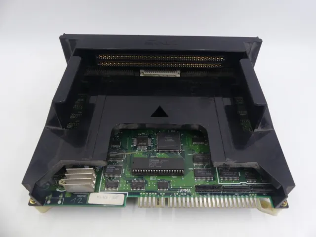
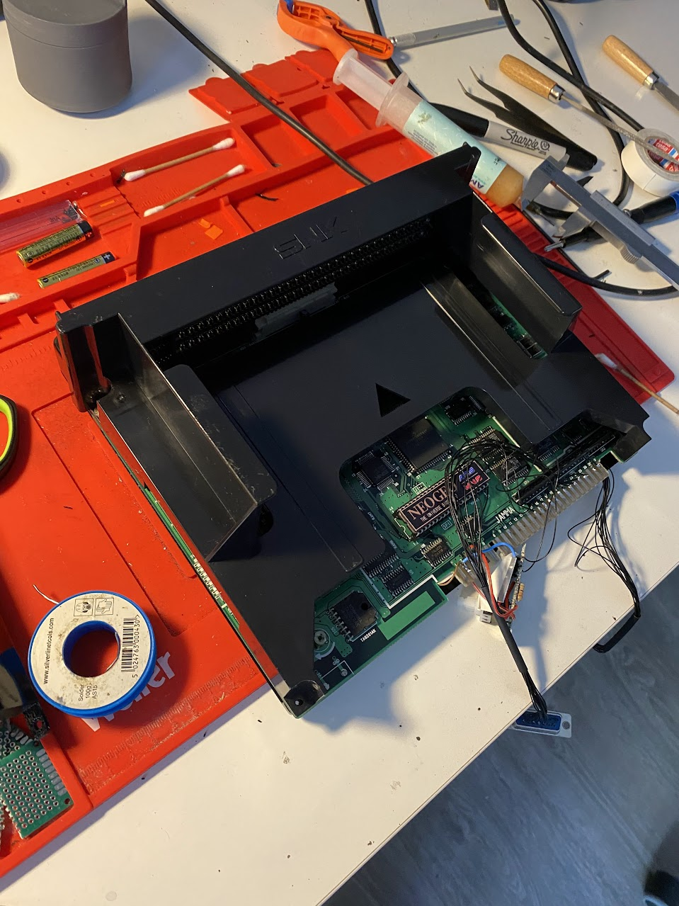
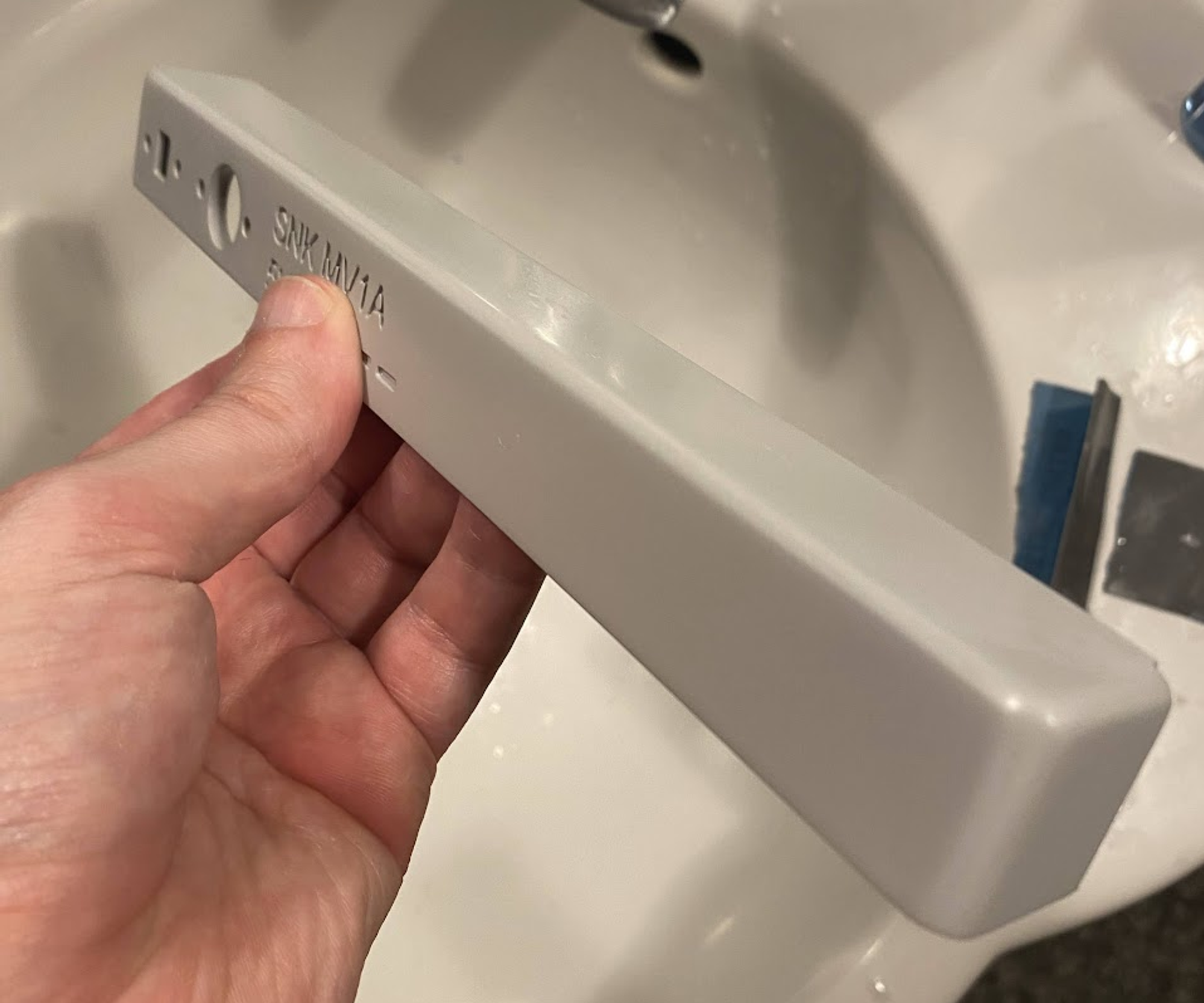
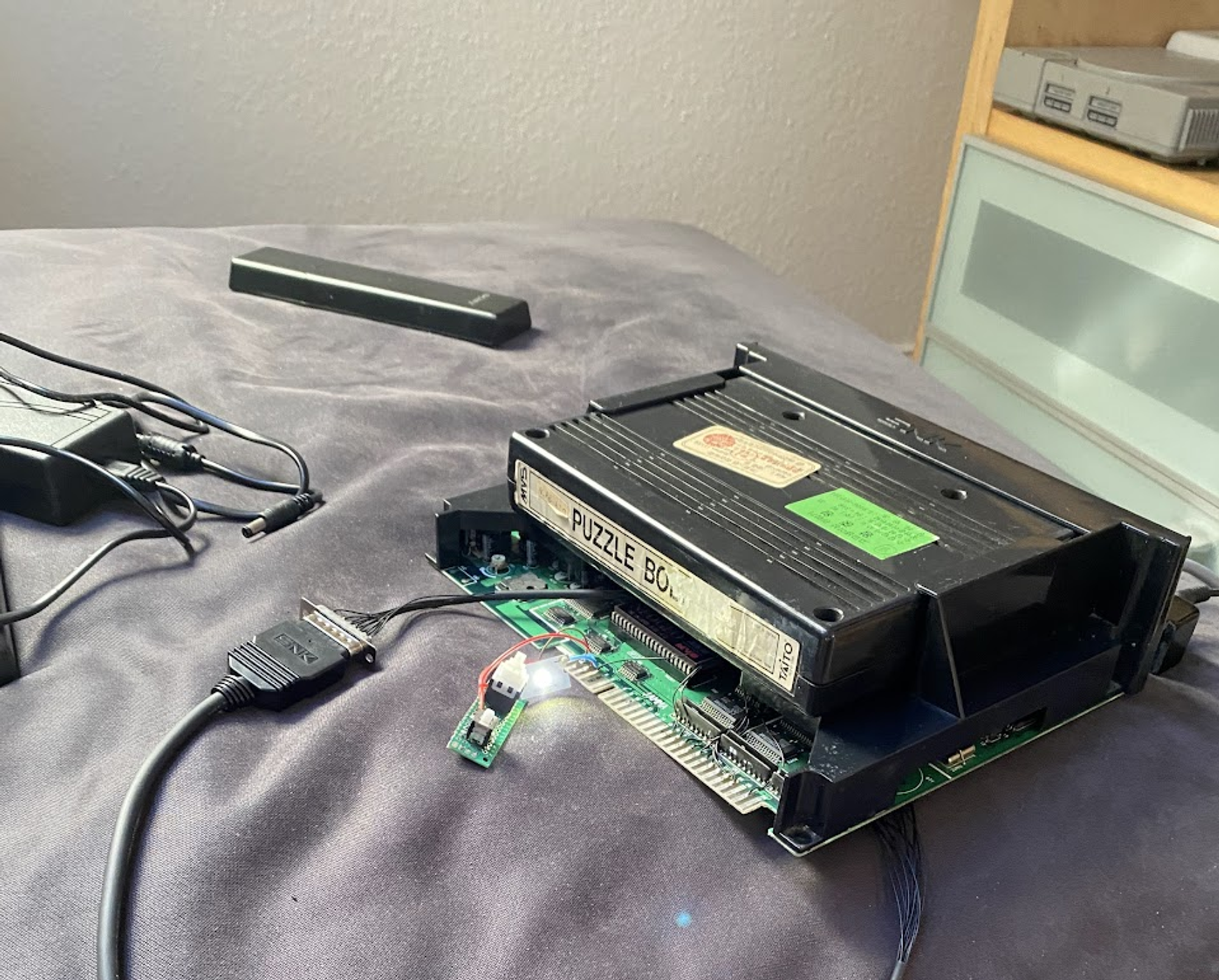
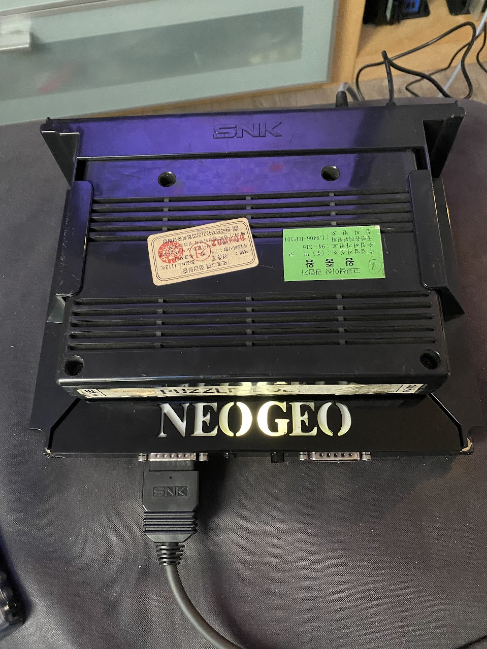
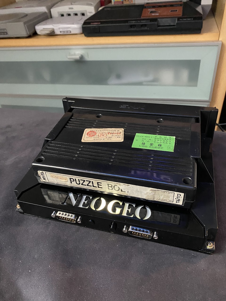
So I got an SNK MV1A board that I wanted to consolize to add it to my collection of consoles. I don’t have an actual picture of mine when I got it but it is basically this board.
When I bought my NEO-GEO AES it came with a UNIBIOS kit that I did not use since I’m planning on getting a NeoSD AES Pro from TerraOnion, so I decided to use it in this build because the MV1A came with the BIOS already socketed.
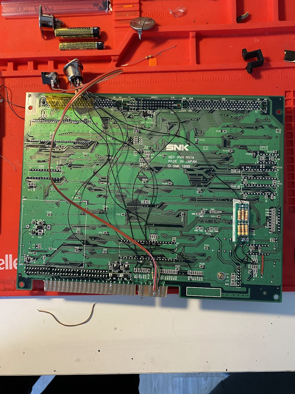
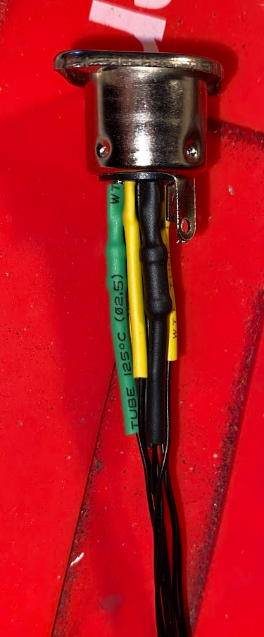
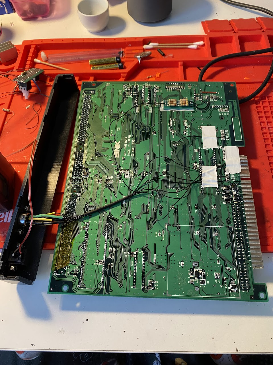
First step was to check that the board actually works. For this, I bought a Puzzle Bobble cart and made some solder work in the board to check that Power, Video and Audio were working. I’m using an 8-PIN DIN socket for getting Video and Audio out, and some junk power connector for Power.
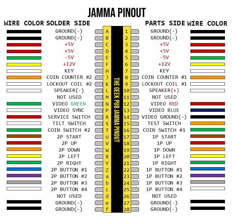
Most of the information for the connections was taken from this article I found online.
Video
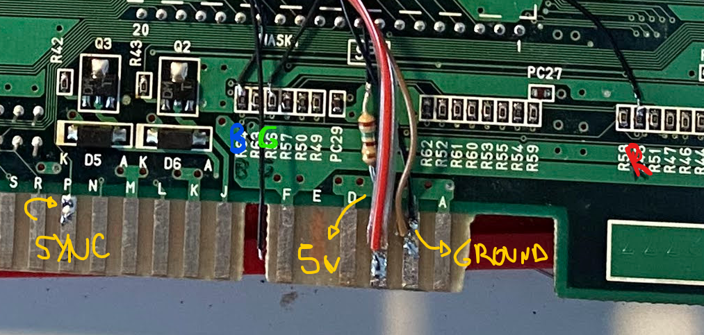
For RGB output I used the following points. Note: Composite SYNC is not connected just because I noticed after taking the picture.
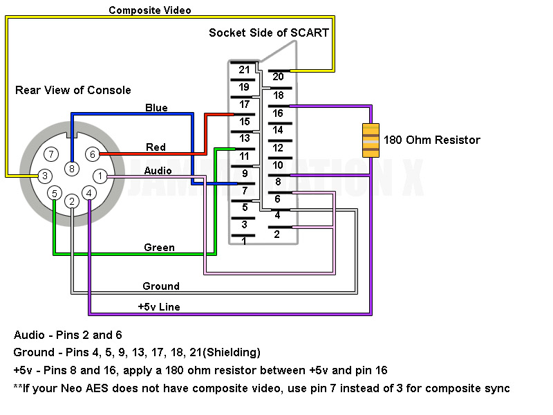
And the following schematic was used to wire to the 8-PIN DIN
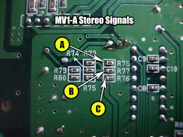
Audio
There is an Stereo mod that requires a board to be built (It is explained in the linked article above) but I decided to go with Mono since my cable did not support Stereo.
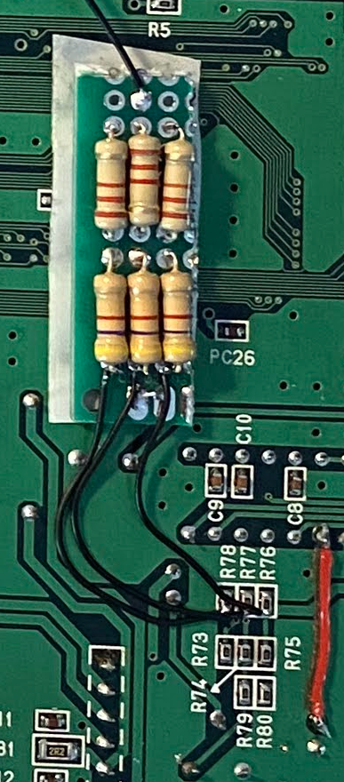
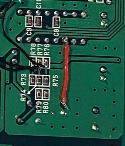
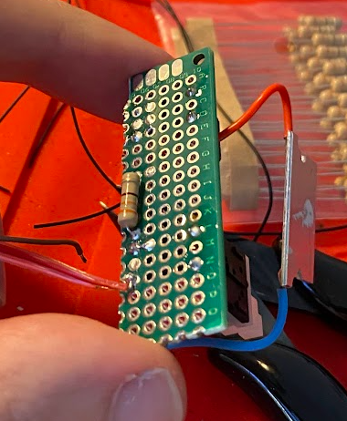
I used some resistors to tap out Mono audio from it by just using some resistors to mix the audio signals. The values from the 2 resistors in each signal line sum up to 6.9K ohms.
Audio sounds good except for a buzzing sound that is only noticed when volume is fairly up, I can live with that for now but I don’t know the real reason. Maybe is the cheap solution to tap Mono audio or maybe the resistor values.
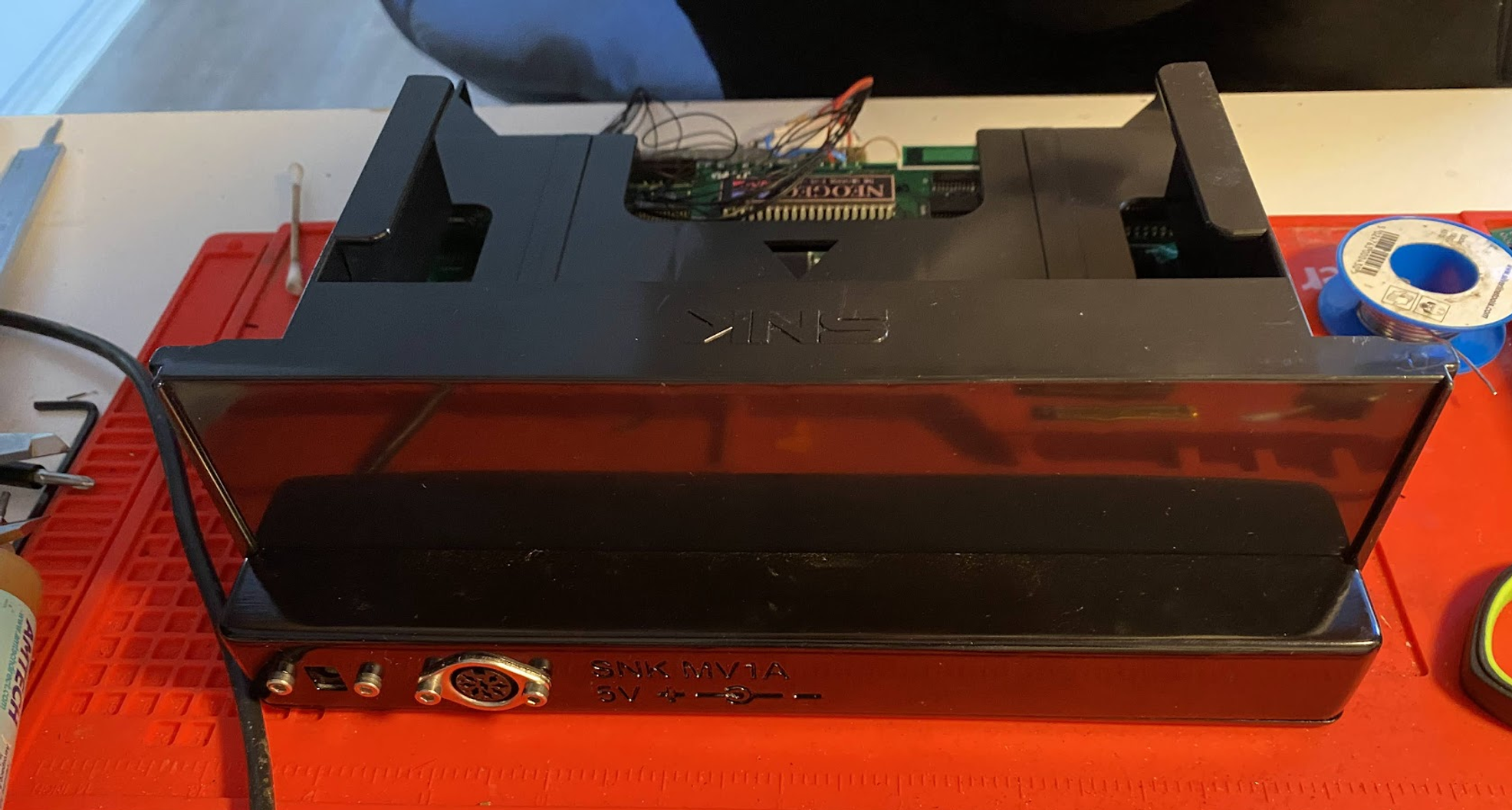
Power
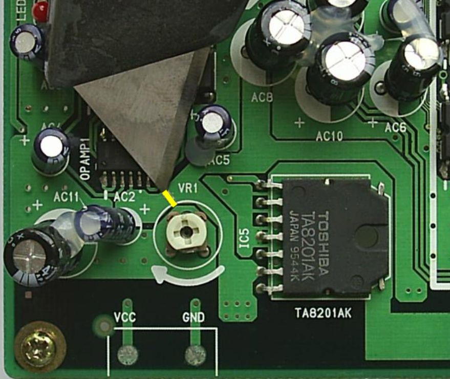
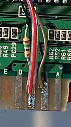
First I needed to make a little mod for the Audio chip to use 5V instead of 12V. Basically you just need to cut the 12V rail to the audio chip and put some bodge wire to supply 5V to it.
Then just connect the live wire from the power connector to the 5V rail and the ground to the Ground rail. To get the power I used a 5V 2A brick I had lying around. Note: The resistor is for the 5V pin on the output connector.
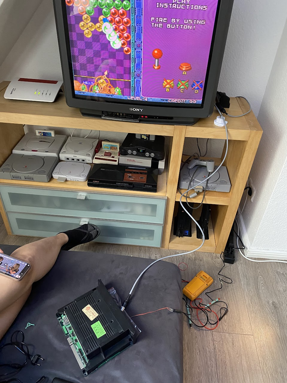
IT WORKS!
Controller ports
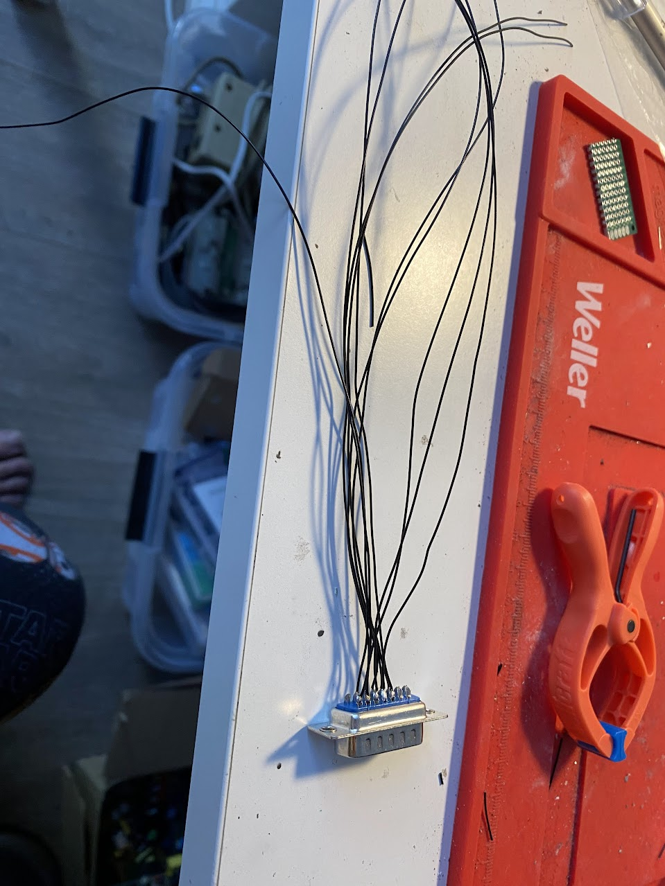
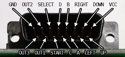
Now that is known to work, it was time to wire up controllers. I plan to use my AES controllers so I got 2 DB15 male connectors for the ports.
I used these images as reference for wiring up the ports. I used the SELECT button on my AES controller as Coin Switch for the board which does not make too much sense since the board is configured as FREE PLAY. I have seen others using it for GAME SELECT or something like that but I believe it is only useful when you have a multi cartridge board.
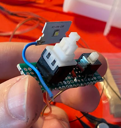
Power Switch
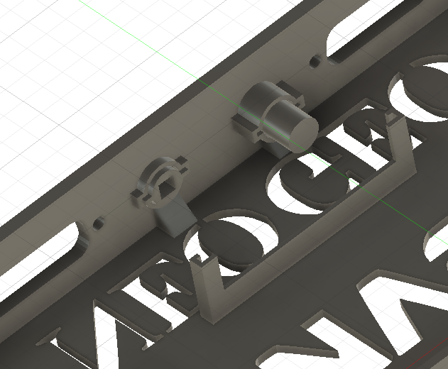
I needed to build a power switch so I took out the buttons from a PS1 broken PSU and made a little board with one button for POWER and the other for RESET. Later I will realize that there is no need for a RESET button so I just reused it as TEST button (TEST mode let’s you configure some settings for the board). I also added a white LED that I took from a bike lamp, this will add up really good to the aesthetics I wanted to achieve.
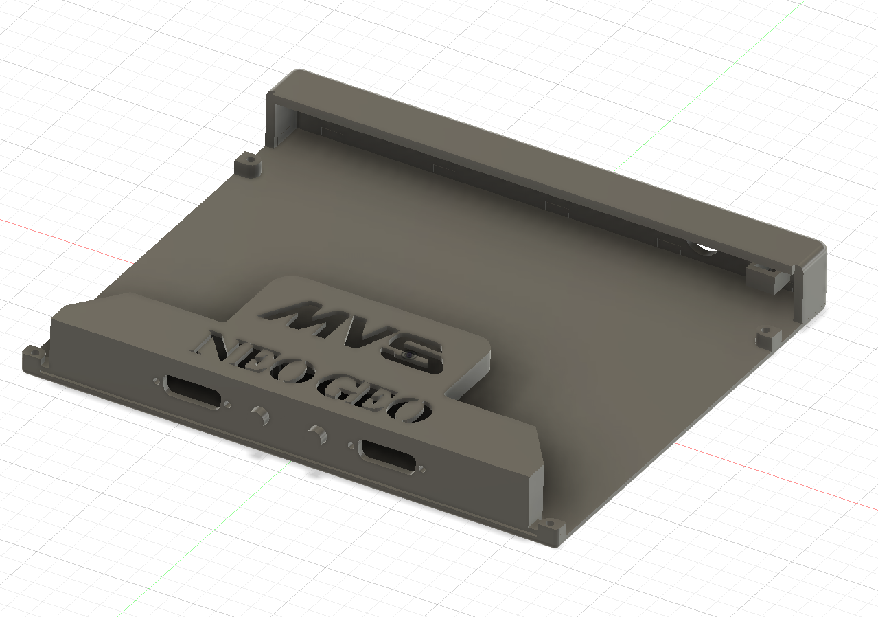
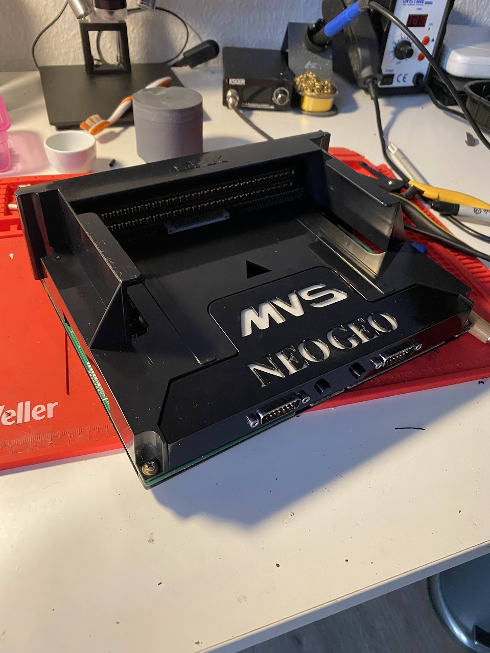
Printing a case
For the containing case I took an existing 3D model I found online and built on top of it. This took a lot of time between measuring, printing a test, re-measure, printing, etc. I used a Prusa MK4S for it and whatever PETG filament colors I had laying around.
Finally, I was able to print everything (I had to reduce a little bit the bottom plate since it won’t fit in my Prusa :P) and after making some adjustments by cutting and filing I had something that I was happy with.
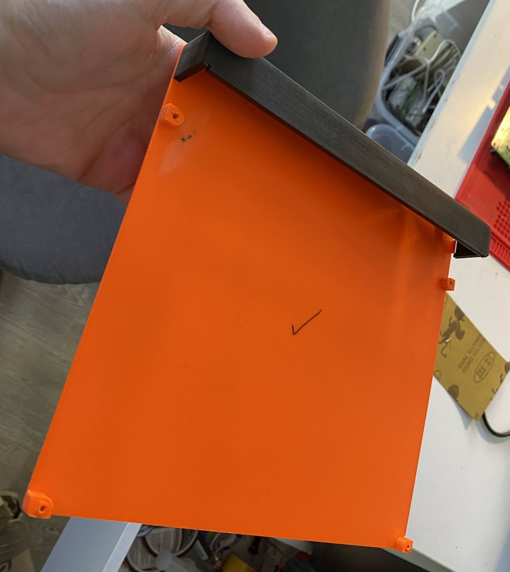
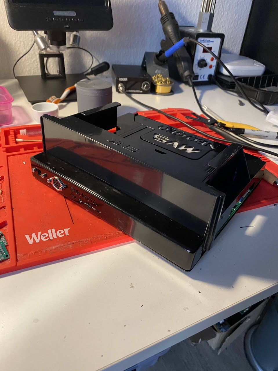
It was time for some post-processing. I used a canned primer, applied 3 coats of it to each part and a lot of sanding between layers.
After a while I was happy with the result and it was time for painting…
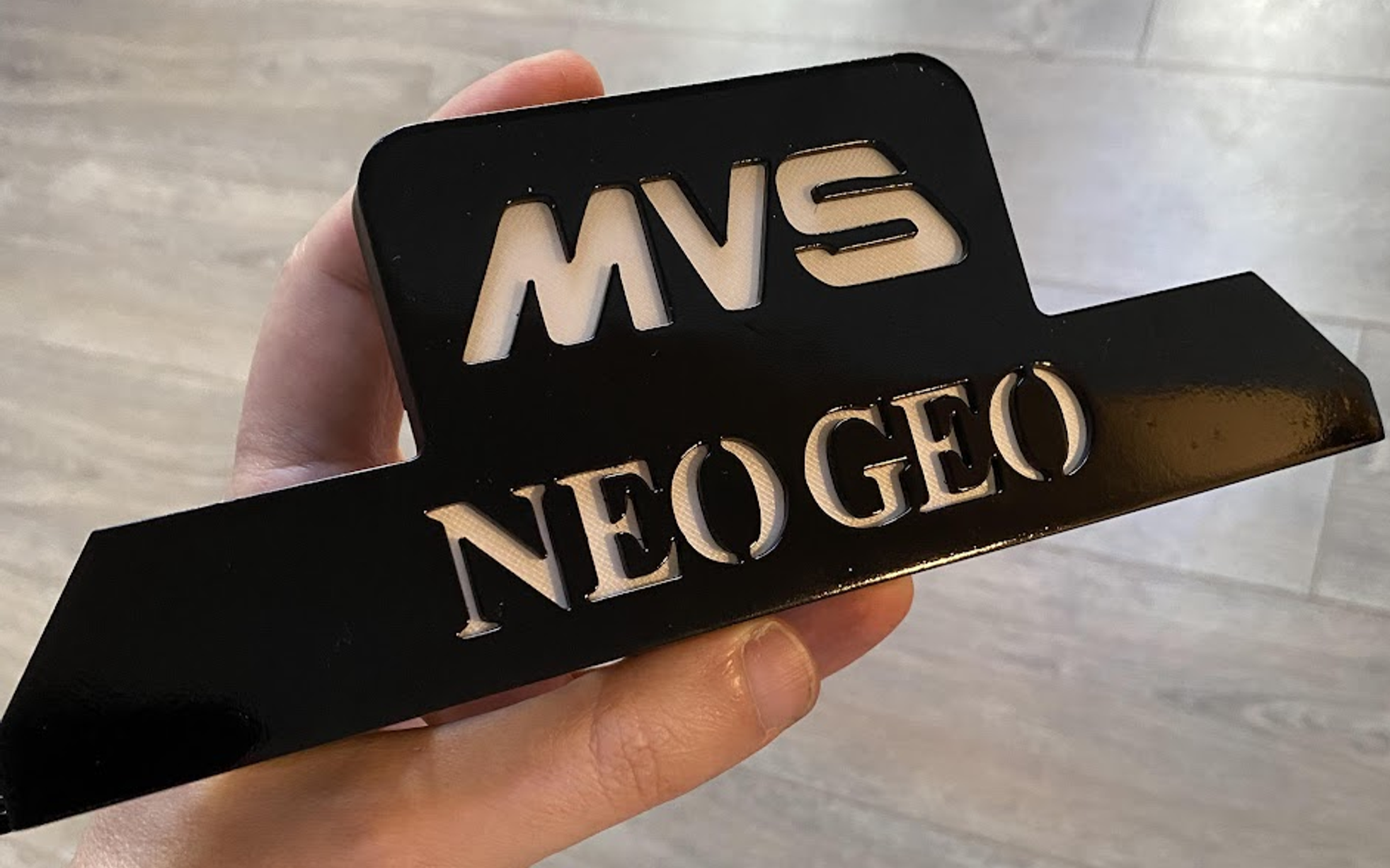
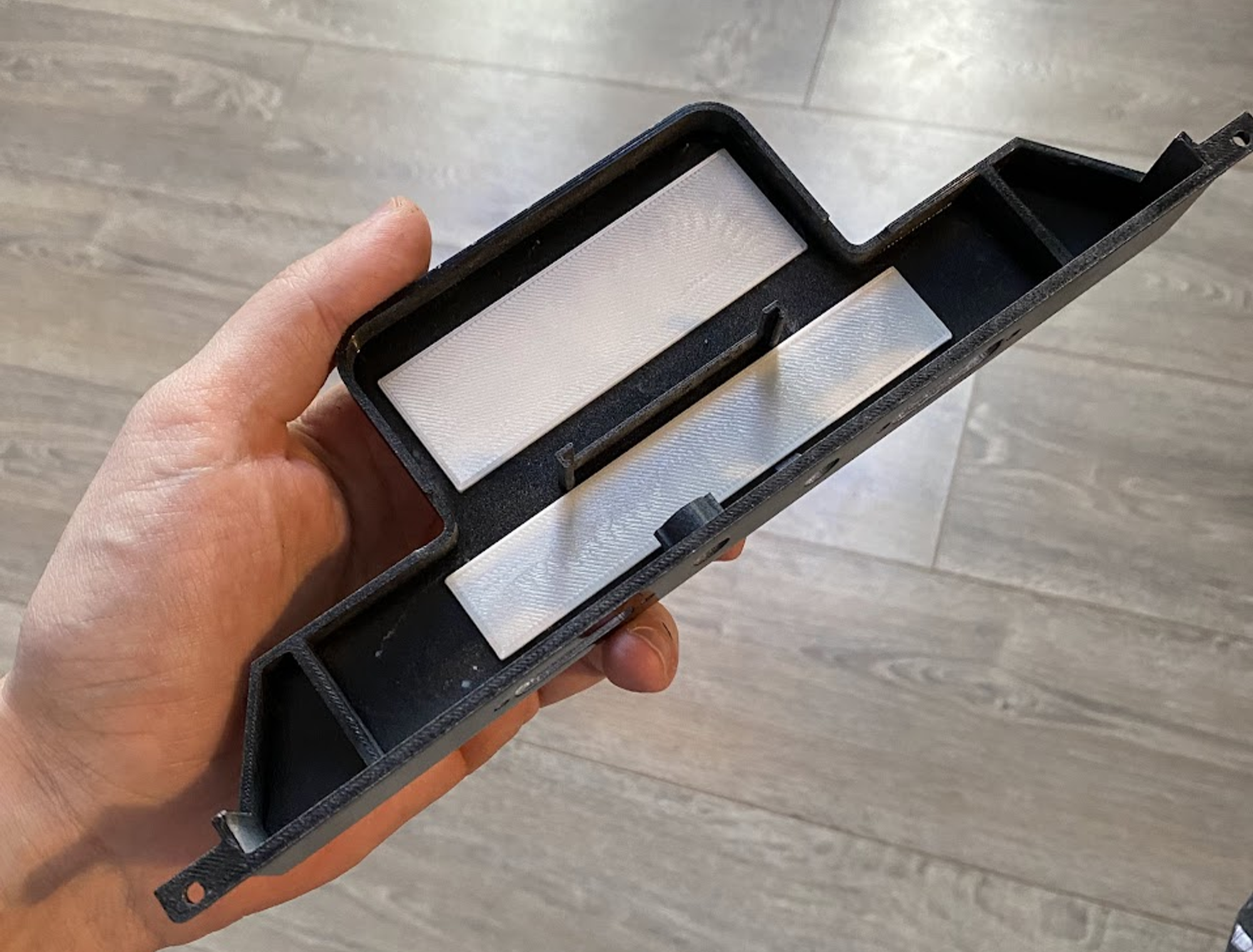
I glued 2 pearl white 2mm thick rectangles to the back of the logos to make the white LED shine through them
Finishing it….
Wiring everything up.
Some more testing…
Assembling the back, I used some spares bolts and nuts from my MK4 Upgrade Kit to fit everything
Finally, after 1 week and a lot of work…
Conclusion
So it took me a lot of effort to make this build happen but the final product is almost exactly what I had in mind so I was really happy with the result. I would liked to have an extra white LED to light up the logo more equally but I could not find any at home. Maybe in the future.
Most of the information was taken from the following sources: